| +Home | Museum | Wanted | Specs | Previous | Next |

NCR 18-2 Electronic Desktop Calculator
Updated 10/16/2025
Like so many other tidbits of history that are being lost every day, the historical details behind the full story of NCR's foray into the electronic calculator market may perhaps be lost. NCR's own web site has no information about the company even having been in the calculator business. There is a large following of collectors that preserve and document NCR's wonderful cash registers, but there's virtually no information anywhere about NCR's calculator history. The hope is that someone who was connected with NCR back in those days (1968 through around 1971) will read this and get in touch with the museum. If you know anything about the history of NCR's calculator business, or the company's relationship with NCM/Busicom, please help add to the story of NCR's foray into the electronic calculator marketplace by clicking the EMail button at the top of this page to send the museum a message. Even if you weren't directly related to NCR, but perhaps sold NCR-branded calculators as a salesperson in an office machine supply company, or perhaps serviced the calculators as a member of a service team at an NCR-authorized service center, the museum would really appreciate hearing from you.
Another View of the NCR 18-2
The 18-2 is the entry-level machine amidst the two NCM-made machines that
brought with them NCR's debut into the electronic calculator marketplace
sometime in the early part of 1969.
Along with the $1095 Model 18-2 exhibited here, the Model
18-3
stable-mate was the flagship machine, with all of the features of
the 18-2 along with a one-key automatic square root function.
for a suggested retail price of $1,275. Both the NCR 18-2 and 18-3 are
identical (other than minor cosmetic differences) to the Model 162-C and
162 (respectively) calculators marketed by NCM under the Busicom brand in
Japan and later in the US. The NCM versions of these calculators preceded
the NCR versions of the machines to market (in Japan) by a period of about
four to five months.
One fact that is not commonly known
is that the only difference between the Busicom 162C/NCR 18-2 and
162/18-3 models is the keyboard assembly. Both machines have
identical electronics, meaning that the Busicom 162C and NCR 18-2 have all of
the necessary circuitry to perform square root, they just do not have a key
on the keyboard to activate the square root function. The Busicom 162C/NCR 18-2
have a double-width backarrow key and a single key-switch for the backarrow
function, while the Busicom 162/NCR 18-3 keyboard assembly has two
separate key-switches, one with a normal-sized backarrow key, and the other
with the square root key. A Busicom 162C/NCR 18-2 can easily be converted
to a 162/18-3 by installing the keyboard assembly from a 162/18-3.
A number of NCR 18-2 calculators have been found that have benefitted from
this modification, with all external and internal nomenclature indicating
a model 18-2, but with the calculator having the square root function.
It is even possible (though not yet documented) that NCR may have
offered this as a field-installable upgrade to the 18-2 calculator
through their service organizations. What is documented, however is
the difference between the 18-2 and 18-3 calculators, which is
is clearly stated in a document published by NCR entitled
"CLASS 18 TECHNICAL INFORMATION HANDBOOK". This paperback document
was copyrighted in 1969, and has the date of February 24, 1969 on the inside
front cover. On the INTRODUCTION page at the front of the document, it states:
The 18-2 was quite a capable machine for the time. It performs the four
basic math functions, offers a full sixteen digits of capacity, and two
independent memory accumulators. The calculator uses mixed floating/fixed
decimal point logic, with a thumb-wheel selecting the fixed decimal point
location (at 0, 1, 2, 3, 6, or 9 digits behind the decimal point) for
addition and subtraction (as well as recall of items from memory registers),
and automatic decimal placement for multiplication and division operations.
This mixed-mode decimal point logic is somewhat unusual, and takes a little
getting used to, but is flexible and affords the greatest accuracy
when multiplying and dividing. Other features include
a convenient [←] key that deletes the last digit entered for
easy correction of mis-entered numbers, and a "clear indicator" [CI] key for
clearing the display without disrupting calculations in progress, also useful
for correcting input errors. For a retail price of just under $1,100, the
NCR 18-2 was quite competitively priced against competitors like the
Monroe 990, a contemporary of the 18-2 with
similar capabilities priced at $1,250.
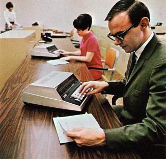
Use of NCR Class-18 Calculators in a Financial Office
The cabinet of the 18-2 is all-metal, with the only plastic
part of the cabinetry being the smoked plastic display window that the
Nixie tubes show through. The base of the machine is a thick metal
casting, with nicely machined bosses for the electronics of the calculator to
mount to. The upper half of the case, again all metal, is a thinner-gauge
casting, but still quite hefty. The upper half of the case fastens to the
base via four screws that are easy to access, which make it easy for
service personnel to access the inside of the calculator.
Overall Internal View of the 18-2 The chassis of the machine is a
combination of stamped metal parts and plastic. The backplane, situated along
the bottom of the chassis, is built upon the heavy metal casting
that makes up the base of the chassis, mounting on the bottom half of
the cabinet. The circuit boards plug into a plastic frame that provides
card edge guides that align the cards and keep them from moving around
during transport. A stamped metal panel covers the top of the card
cage to keep the circuit boards from working themselves out of the connectors
they plug into.
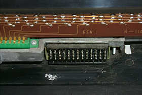
The Keyboard Connector The keyboard assembly, a rather massive
item by itself, is built on a stamped metal frame that sets into plastic
section of the chassis. A large multi-pin connector provides the electrical
connection between the keyboard and the backplane. The design is such that
getting the keyboard disconnected from the connector is difficult, because
the cables are short enough that the keyboard assembly can't be lifted too
far, meaning that it takes small hands to get under the keyboard while
holding it up. Plugging the keyboard connector back in after the keyboard
has been removed is even more challenging.
The "Business" side of the keyboard The keyboard design is quite unusual,
using leaf-type contacts actuated by the plunger of the key-stalk. Most
calculators of the time used magnet-actuated sealed reed switches, which provide
a much cleaner switching action (less contact bounce) and offer
longer service life. The leaf-switch design was likely used to
help reduce the cost of the calculator, however, this
seems somewhat contradictory, though, given that the rest of the machine seems
to be built with long-term reliability in mind.
A close-up view of the key-switch modules in the NCR 18-2 Each switch has a fixed set of contacts
and another contact that moves. When the key is depressed, the plunger
pushes the movable contact aside as it moves downward, causing it to come
into contact with the fixed set of contacts. A capacitor mounted directly
to the leads of the switch helps absorb some of the switching transients
caused by the mechanical action of the switch. Other circuitry helps clean
up and shape the switch closure waveform so that reliable key presses are
detected. Each switch is encased in a snap-on clear plastic housing that
keeps out dust, but allows removal for adjustment and cleaning of the switch
contacts by service personnel.
The Backplane of the NCR 18-2 The backplane that provides interconnection
between the circuit boards, keyboard, power supply, and display subsystem
is hand-wired, with point-to-point connections painstakingly made
by workers that had to have immense patience to be able to do this type
of wiring day-in and day-out. Each of the ten circuit boards that make
up the logic of the machine plugs into four edge-connectors in the backplane.
Each connector has twenty gold-plated contacts, for a total of 80 possible
connections for each circuit board. One extra set of two edge connectors
provide an eleventh slot for the display subsystem to plug into.
The Power Supply of the NCR 18-2 The power supply for the machine takes
up the back portion of the chassis, and, like most of the other aspects
of this calculator, seems nicely over-built. It is a complex power supply,
with it appearing that all voltages (with the exception of the Nixie
tube drive voltages) being transistor-regulated, and heavily filtered.
Power supply voltages are +4.5 Volts DC for the logic supply for the
Diode-Transistor Logic (DTL) integrated circuits; +6.5 Volts (variable within
a range (+5.5V to +8V) based on temperature) for the core memory driver
circuits; -10 Volts DC also used as a bias voltage in the core memory
system; +100 Volts DC used as the cathode supply for the Nixie tube display;
and +200 Volts DC for the Nixie tube anode supply.
Detail of the 18-2's Nixie Display (note lit "Overflow" Indicator) The display subsystem of the 18-2 is
a modular assembly that plugs into the backplane. The subsystem consists
of a circuit board to which the Nixies are soldered, with a fairly elaborate
metal frame to align and secure the display tubes. A metal bezel with stamped
digit designator nomenclature presents the faces of the Nixie tubes to
the user. Along with the sixteen Nixie tubes, which have 5/8-inch tall
digits and a right-hand decimal point, are two incandescent lamps situated
behind jewels at the left end of the display that light up to indicate a
negative number and/or overflow of the calculator.
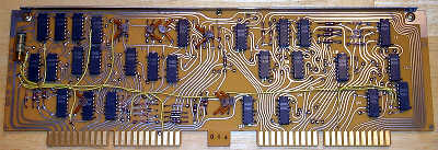
A typical logic board from the NCR 18-2 The 18-2 uses small-scale integrated
circuits for its logic. A total of 134 Signetics-made DTL integrated
circuits combine forces with a 256-bit core memory array, and an assortment
of diode-resistor logic and other discrete components to make up the
logic that operates the machine.
A close-up view of one of the IC's (Signetics ST670A Triple Three-Input NAND Gates)
A total of four different IC part numbers are all that are used in the
machine. The devices are from Signetics' SP/ST 600A low-cost, high-reliability
DTL integrated circuit family. The four devices used are the ST616A
Dual Four-Input Expandable NAND gates; ST629A Single RS/T Flip Flop;
ST670A Triple Three-Input NAND gates; and ST680A Quad Two-Input NAND gates.
Each circuit board is approximately
11 inches wide by 4 1/2 inches tall, and is made of a phenolic circuit
board material. Edge connector fingers are gold-plated, which makes for a
very reliable and corrosion-resistant connection. Components are mounted
only on the front of the boards, with interconnection traces etched on both
sides of the board. Feed-throughs connecting the two sides of the board are
implemented by placing a pad on each side of the board, with a hole drilled
through. A piece of wire is inserted in the hole and soldered on each side of
the board. Jumper wires are occasionally used on either side of the board
to provide interconnections when etched traces couldn't be routed.
A metal stiffening bar is riveted across the top edge of the circuit board
to provide some structural rigidity for the boards.
The circuit boards are numbered one through ten, with board #1 closest
to the front of the machine. Board 1 contains the add/subtract and memory
total control logic, binary full adder, clear function Logic, negative
indicator driver, sign determination logic, and decimal point placement
logic for divide and square root. Board 2 provides sequence control logic
for multiply, divide, and square root, as well as overflow detection for
multiplication. Board #3 contains
three counters designated Y, Z, and MQ that are used in all operations of the calculator, along with logic for
right-shift control and the round-off. Circuit Board #4 has the
master clock generator and timing chain logic, register selection control,
shifting control, and memory 1 round-off logic. Board #5 contains a
sequencing counter, operation start control logic, right-shift
gating logic, numeric entry control, function control logic, overflow control,
and left shifting of the decimal point when digits are entered behind the
decimal point. Board 6 contains overall decimal point placement logic, as
well as additional divide and square root sequencing logic. Board 7 contains
the magnetic core memory module, core memory column current sources and sinks,
and four core memory sense amplifiers. Board 8 has the core memory row
current sources and sinks, and sense amplifier strobe timing. Board 9
provides the Nixie tube display anode drivers, more numeric entry logic and
additional logic for divide and square root functions. Lastly, Board 10
has the Nixie Display cathode drivers, numeric entry decoding, and function
key decoding and storage.
The Core Memory Board (Core Array at Center) At the time this machine was designed,
during the late part of the 1960's, the levels of integration possible
in IC technology were such that it wasn't practical in most cases
to implement the operating registers of an electronic
calculator using individual flip flops.
Some of the Japanese MOS (Metal-Oxide Semiconductor) IC's could implement
a 10 or 12-bit shift register in a single chip, but even at that level of
integration, it would require quite a number of IC's to implement all of
storage required for the working registers of a calculator with the
capabilities of the NCR 18-2. The
NCR 18-2 uses a small magnetic core memory array, manufactured by Japanese
electronics component and equipment manufacturer Mitsubishi, as its register
storage system. The core array consists of four 8x8 core planes for a total
of 256 bits of storage. Magnetic core memory uses small doughnut-shaped
rings of ferrite magnetic material, woven into a grid of wiring that
allows each individual core to be magnetized in one direction or another,
as well as allowing the magnetic state of each core to be individually detected.
With such an arrangement, it is possible to store the working registers
of the calculator (the display register, a working register, and the two
memory registers) as a series of magnetic ones and zeroes within the
core array. Magnetic core memory technology evolved out of work by Dr. An Wang,
a pioneer in the field of magnetic core memory technology, and later,
the founder of Wang Laboratories, a company that made a fortune in the
high-end electronic calculator business from the mid-1960's through the
late 1970's.
Keyboard Detail on the NCR 18-2 The color scheme of the NCR 18-2's keyboard
is somewhat odd, potentially as a result of some key caps being replaced
over the life of the machine. Key caps are colored white, ivory, beige,
or gray, in a mixture that doesn't seem to correlate with their function.
The [4] and [6] keys are white, while the rest of the digit keys are ivory
in color. It seems that perhaps the [4] and [6] key caps were replaced,
and at the time they were replaced, there were differences in the color
of the replacement keys, or the difference could be that the
[4] and [6] are newer and haven't discolored from as much as the other digit
keys
Another example is the [X] key, which is gray, while the
other math function keys are beige. Perhaps the [X] key was also replaced
and somewhere in the process, the colors were changed. In any case, key cap
coloring aside, the layout of the NCR 18-2's keyboard is logically thought-out
and attractive from an aesthetic point of view. There are four groups
of keys, with the left-most group providing miscellaneous functions, including
the [→] key, memory register recall and clear keys, along with the
clear all and clear indicator [CI] keys. The next group of keys is the
traditional numeric keypad, with oversized [0] key, and a raised area
on the [5] key to allow the user to orient their fingers on the keyboard
by touch. The math functions make up the next group of keys, with the
memory accumulation function keys in the last group.
At the left end of the keyboard assembly
is a thumb-wheel switch that is used to select the decimal point position
for addition, subtraction, and memory recall operations. The decimal point
selection thumb-wheel provides selections for 0, 1, 2, 3, 6, and 9 digits
behind the decimal point. Above the decimal point selection thumb-wheel
is the push-on/push-off power switch. At the right end of the keyboard,
a three-position slide switch selects the rounding mode of the calculator.
The switch has no detectable nomenclature on the keyboard panel, either
it was never there, or the nomenclature was printed on the keyboard panel
in such a way that it wore off over time and usage. The rounding mode
of the machine operates only with addition and subtraction operations, where
the fixed decimal point setting of the machine comes into play.
The uppermost position of this switch forces the calculator to round the
least-significant digit up in all cases. The center position of the
rounding switch causes the calculator to round up if the next less-significant
digit is five or greater, and to truncate if the digit is four or less.
The lower-most position of the rounding switch causes the calculator to
ignore the next less-significant digit, leaving the least significant
digit alone in all cases. As an example, performing 1 divided by 3, followed
by pressing the [+] key (thus forcing the machine to fix the decimal
at the selected position), with the decimal position set to '2' would
result in: 00000000000000.34, 00000000000000.33, and 00000000000000.33
with the rounding switch in the upper, middle, and lower positions.
Performing 2 divided by 3 with the same settings would result in
00000000000000.67, 00000000000000.67, and 00000000000000.66.
The Model/Serial Number Tag on the NCR 18-2 The 18-2 uses the usual-for-the-time
mix of algebraic and arithmetic logic. Addition and subtraction operate
arithmetically, with the function entered after the operand, like an
adding machine. For example, to subtract 15 from 30, the problem would
be entered as '30', [+], '15', [-], with the result of 15 showing in the
display after the [-] key is pressed. Multiplication and division
are entered algebraically, with the [=] key completing the operation.
As mentioned before, the decimal point location in multiplication and
division is fully floating, with the calculator placing the decimal point
wherever needed to wring the maximum accuracy out of the result. However,
as soon as a result of a multiplication or division is submitted for
addition or subtraction, or stored in a memory register, it is forced
to the number of digits behind the decimal point as selected by the
decimal point selection thumb-wheel (and rounded according to the setting
of the rounding mode switch).
Internal QA and Modification Record Tag (located under the keyboard, glued to the cabinet base) The memory capabilities of the 18-2 are
quite handy, with two completely independent accumulating memory registers.
Each memory register has keys to clear, recall to display, add to memory,
subtract from memory, and add product/quotient (acting as "=", followed
by add to memory function) to memory. The memory registers adhere to the
decimal point location selected by the thumb-wheel, with rounding occurring
as defined by the position of the rounding mode switch. The memory registers,
although residing in non-volatile core memory, are automatically cleared
when the calculator is powered up, so it isn't possible to recall a number
in a memory register after a the calculator has been powered off, as
can be done on some other calculators using magnetic core memory that
don't clear the core memory at power-on time.
The NCR 18-2 does have a few quirks
in its operation. Division with dividend larger than 14 significant
digits causes incorrect results. This is a common limitation on many
electronic calculators of th era, mainly because two
digits in the working register are used as temporary counters
during the division calculation. The overflow detection on the machine is
a bit dicey, sometimes failing to indicate an overflow (mainly in
large multiplication operations) when one should occur. When an overflow does
occur, the keyboard is not locked out, meaning operations can continue,
although the results obtained when the calculator overflows
are generally useless. Division by zero results in the machine becoming
quite confused, causing it to become unresponsive to any keyboard input
except the [C], or [CI] key, which will stop the futility of the effort, though
pressing [CI] leaves the machine in a strange state, requiring a full
clear (using the [C] key) to restore it to normal operation.
The 18-2 is not a speed demon, with
some division operations taking nearly a second to complete. The "all nines"
(which in this case, is 14 nines due to the limitation mentioned above) divided
by 1 division problem takes just a shade under 1 second to perform. During
the calculation, the Nixie tubes put on quite a light show, as the displays
are left active as the calculator subtracts, shifts, and accumulates the
quotient. Manufacturer-stated calculation times are 430 milliseconds
(0.43 second) maximum for multiplication, division and square root. Addition
and subtraction are quoted as taking 20 milliseconds (0.02 seconds).
Generally the manufacturer-quoted calculation times are averages rather
than worst-case.

"Two models of the C-18 are available.
The C-18-3 is the basic machine and contains all of the features listed above. The C-18-2 contains all of the features of the C-18-3 except square root
feature."
The features list mentioned discusses the common features of the two
modules, including two memory registers, 16-digit
display, integrated circuit logic elements, plug in cards and
assemblies, selectable round-off features, automatic decimal
set feature, overflow indication, and addition, subtraction, multiplication, division, square root, and right-shift operations.