
| +Home | Museum | Wanted | Specs | Previous | Next |

Canon Pocketronic Electronic Calculator
Updated 3/9/2021
The Canon Pocketronic is a history-making calculator, being the first handheld battery-powered printing electronic calculator. The Pocketronic was also one of the earliest calculators to use Large Scale Integrated(LSI) Circuits to provide the logic for the calculator, making it small enough to be easily carried around as opposed to other printing calculators of the day that were desktop-bound. Along with making history as the first handheld printing calculator, the Pocketronic also has an interesting history behind its development.
The concepts behind the Canon Pocketronic were actually created nearly five years before the introduction of the machine by a skunk-works project at Texas Instruments. As an outgrowth of the project, Canon and Texas Instruments collaborated to introduce the Pocketronic in Japan in the fall of 1970, and in February of 1971 in the United States. Slightly later, Monroe announced the Monroe Model 10, a repackaged (with a softer, more rounded look) Pocketronic as part of their OEM relationship with Canon.

The Monroe Model 10 clone of the Canon Pocketronic
Before going into detail about the Pocketronic, the story of this secret calculator project at Texas Instruments is important to know. The story is a fascinating tale of innovation, perseverance, and the magic that can be created when the right team of people come together with a lofty goal. Initially, the thought of such a project seemed laughable at the time. Even though technology was advancing at a record-setting pace, it still seemed an extraordinarily daunting challenge to have this project produce anything tangible.

The Cover of the Instruction Leaflet for the Pocketronic
In 1965, Texas Instruments(TI) had pretty much perfected its technology for small-scale bipolar integrated circuit devices, each of which could contain from four to perhaps twenty logic elements. The market for these devices was mainly commercial; computer manufacturers, industrial control manufacturers and military electronics contractors. TI executive management felt that the way to really increase the sales of their integrated circuits was to come up with a consumer product that could use integrated circuits, most importantly, Texas Instruments-made integrated circuits, in an application that would be irresistible to the general public. Along with this, TI needed an internal initiative to drive its IC technology to the next level. TI's management knew that other IC manufacturers, such as General Micro-electronics(GM-e), Rockwell's Autonetics division, and NEC and Hitachi in Japan, were working to make higher density integrated circuits, and it was just a matter of time before these competitors would be able to produce large-scale integrated circuits.
In fact, GM-e had already developed a series of 23 densely integrated Metal Oxide Semiconductor(MOS) devices that were being used to develop a desktop electronic calculator for Victor Comptometer, and in April of '65, had delivered 25 working prototype calculators to Victor. The resulting Victor 3900 calculator represented a historically huge advancement in the state of the art, both in the ICs that made it up, as well as their application in a desktop electronic calculator. The Victor 3900 is considered to be the first commercial electronic calculator with its logic implemented entirely by digital integrated circuits, as well as being the first marketed electronic calculator to utilize so-called "Large Scale Integration" MOS devices. The 3900 was truly a breakthrough. Perhaps some knowledge of the existence of this calculator may have driven the efforts within Texas Instruments to look into the application of large scale ICs in the development of a portable, battery-powered electronic calculator.
Along with GM-e's work, Hayakawa Electric (Sharp Corp.) in Japan had also been spending a lot of R&D money on the design of a simplified electronic calculator that would utilise large-scale MOS ICs for its logic, with the goal being to drastically decrease the size of a basic electronic calculator such that it could be portable, albeit still tethered to an AC power outlet. As a proof-of-concept, Hayakawa Electric had partnered with Japanese IC manufacture Mitsubishi, whom they had worked with before using a small number of Mitsubishi's early small-scale TTL ICs in a number of their second- and third-generation calculators. This proof-of-concept resulted in a prototype handheld calculator that used eleven highly integrated bipolar IC's, but the machine used a lot of power, making it impractical for eventually running on battery power. After working on the design for MOS Integrated Circuits to leverage their simpler construction, higher density, and lower power consumption for quite some time, it became clear that no Japanese IC manufacturer was yet ready to be able to fabricate the large-scale MOS devices that would be required for Sharp's proposed calculator. In '68, Sharp went looking for a company in the US to make the large-scale MOS chips. Finally, after many rejections from from US IC manufactures, a last minute offer came in from the Autonetics IC development division of Rockwell, and a deal was made whereby Autonetics would develop the Large Scale MOS ICs that Sharp needed. The calculator that eventually resulted was the revolutionary Sharp QT-8D, the "second" (though many historical accounts neglect counting the Victor 3900 as he first) MOS/LSI-based electronic calculator. Although the QT-8D was an AC-powered desktop calculator, it was smaller, lighter, and much easier to move around than any other electronic calculator of the time, and the introduction of a calculator that was built using only four LSI chips came as quite a shock to the industry, and also foretold a large shakeup in the business. LSI ICs made possible dramatic shrinkage of the size and price of calculators and at the same time, their capabilities increased. Later, the same Rockwell-designed chips were used in the Sharp EL-8, the first LSI-based "handheld" battery-powered electronic calculator.
In the mid-1960's, when the genesis of Texas Instruments' calculator project formed, the notion of large scale ICs (devices with over 200 transistors on a single chip) was a concept that very few IC manufacturers had even considered, and those that had were mostly doing research & development work on MOS devices. The only exception was General Micro-electronics, that had actively developed and sold large-scale ICs for US government security and military establishments before embarking on the project for Victor Comptometer.
Texas Instruments' management decided that an internal project to leverage the development of IC's with higher levels of integration would be a good way to engage the creative energies of their best engineers.

Profile View of the Canon Pocketronic
A number of ideas for consumer devices that could leverage IC technology were tossed about, including the idea to build a calculating machine that was battery-powered and portable. At the time, such a machine was nothing but a dream -- the technology simply didn't exist to make such a device. Electronic calculators in 1965 were large, heavy machines that consumed the majority of a desktop. Examples of such machines from that time are the Friden 130, Wang LOCI-2, Mathatronics Mathatron, and Sharp Compet 20, as well as the soon-to-be announced ground-breaking Victor 3900. The limitations of integrated circuit technology, though a big hurdle to overcome, was only part of the technology limitations that the anyone trying to design a small, portable calculator faced. There were issues with battery technology; a compact, low-power method for displaying the results of the calculations; circuit packaging; and keyboard technology that all had to be addressed, making the project a very ambitious and difficult to attain goal. With the challenge defined, a small group of TI's best engineers were selected to work on the project, giving the team access to the resources it needed within TI to make the dream a reality. The internal TI project was code-named "Cal Tech", a reference to famous California-based institution of higher learning. However, though the code name for the project implied a connection to the school, there was really no relationship with the institution. The code name simply followed a pattern that had emerged inside TI for naming internal projects after noteworthy institutions of higher education. As it was later realized, this was a rather obvious "secret code name" for a project involving "Calculator Technology". The project was an internal exercise to stimulate technology development, and was never really intended to become a true product. But, as time later proved, the ideas and technologies that the Cal Tech project created advanced the state of the art of calculator technology in a very tangible way despite never becoming a real product.
The developments by the team that created Cal Tech set the stage for the development of small, portable, battery-powered electronic calculators of the early 1970's that completely changed the market from one of mostly "business machines" to a consumer market, vastly opening up the profit opportunities for any company that could produce the smallest, lightest, lowest-cost, best-featured, longest battery run-time, easy-to-use electronic calculator.

The TI "Cal Tech" Calculator
Image Courtesy of Texas Instruments
At one point, Patrick Haggerty(3/17/1914-10/1/1980), at the time, the President of Texas Instruments happened happened to end up on the same plane flight, sitting right next to Jack Kilby(11/8/1923-6/20/2005), one of TI's senior scientists that had co-invented the first simplistic integrated circuit a few years earlier. The two men chatted during the flight about the possible consumer applications for integrated circuits. As a result of that conversation, the idea of a project to develop a prototype handheld portable electronic calculator came to life. Shortly thereafter, Haggerty gave the project to Kilby as the leader of the team. Kilby's visionary skills, and expert knowledge of integrated circuits made him a perfect choice to lead this project. Kilby quickly added Jerry Merryman(6/17/1932-2/27/2019), a relatively new engineer to TI, to the team. Merryman, in his short tenure with TI, had already earned a great reputation for his tenacious engineering abilities. Merryman's skills were in digital design, an area of expertise that was critical for the design of an electronic calculator. Another member of the team was James Van Tassel, an expert in creation of prototype hardware. Van Tassel had a wide range of skills that would be applicable to the Cal Tech project, including manufacturing, materials science, mechanical engineering, and electronics. Many other folks inside TI were also involved in the project, however, only from a peripheral point of view. Only a small core of people were aware that the pieces of the project they were working on were part of a project to build an electronic calculator. Even though the code name for the project was somewhat transparent, the secret did manage to stay relatively secure within, and outside of Texas Instruments.
The project rolled along at a healthy pace, with a lot of marathon design work. Merryman spent his initial time designing the logic for the machine, while Van Tassel worked on designing a small, easy-to-use, but reliable keyboard for the machine. Once the logic design of the machine was sketched out, Merryman decided to bypass building a prototype of the logic, and instead opted to translate the gate-level design directly to LSI integrated circuits...a bold move, considering that the design hadn't been tested, nor was anyone even sure that the IC's could be built in the first place. The problem was that at the time, most of the IC's built to might contain 20 or so logic elements Merryman's logic design would require about 150 logic elements per chip in order to fit the logic within the confines of a portable hand-held device. Merryman worked very closely with the IC fabrication people at TI, using TI's latest bipolar IC technologies to cram as many devices per chip as possible. Using conservative design rules (design rules are aspects of integrated circuit design that define things like the size and spacing of circuit components, and the width and spacing of interconnections between components), and actually putting more devices on the chip than actually needed (essentially, adding extra 'spare' gates to the chip) to hopefully make the IC's a practical reality. Merryman came up with the idea of designing a chip that had a bunch of the different types of logic elements laid out on it, with the thought that they could perform differing functions by simply changing the way that the logic elements were wired together in the final phases of production of a given chip. After working tirelessly to reduce the logic of the machine down to the minimum possible number of logic elements, Merryman's design was able to fit onto four large-scale bipolar integrated circuits, each containing about 150 individual logic elements. Along with the large bipolar chips that contained the operating logic of the calculator, there were also three medium-scale MOS devices that came out of Texas Instruments MOS R&D Lab; shift-register chips that were used to form the storage for the three working registers of the calculator.
The first runs of the Merryman's ICs were disappointing -- none of them worked. But, Merryman's foresight in over-designing the chips allowed for extra logic elements on each chip, essentially making on-chip spare logic elements. At this point, given that a way needed to be found to figure out what was wrong with the chips, it was clear that some method for testing the chips was needed. While initially, Merryman balked at the thought of a breadboard version of the logic for the calculator, but it became clear this was going to be what was needed. A functional equivalent of all of the logic on the chips was built that used a few hundred of TI's off-the-shelf small-scale integrated circuits. Through use of this large implementation of the calculator's logic, Merryman was able to compare the chip version of the logic with the small-scale IC-based version, and isolate the faulty logic elements on the chips. Once the faults were isolated, "patching" techniques (essentially rewiring defective portions of the chip to utilize the designed-in spare logic elements, all performed under a microscope) were used to fix the defects. Through these methods, a few sets of working IC's were created.

The Cal Tech in Breadboard Form
Image Courtesy of Texas Instruments
In the meantime, Van Tassel had come up with a keyboard design that was small, inexpensive to manufacture, and reliable. Two major hurdles had been overcome. The next step was to figure out how the calculator would display its results. At the time, display technology involved power-hungry Nixie tube or other types of gas-discharge displays that required high voltages to operate. LED's (Light Emitting Diodes) were a only a laboratory curiosity at the time, and LCD's (Liquid Crystal Displays) did not exist yet. None of the existing display technologies seemed suitable. One of the noted weaknesses of existing display-type electronic calculators was that there were very few that could generate a hard-copy of their output, and the few that could were extremely expensive. It was decided that rather than simply displaying the results, some form of printing output would work better, both providing a usable hard-copy of calculations, as well as being able to be made small-enough and consume little power for use in a battery-operated calculator. A good part of the market for such a calculator would be for accountants and bookkeepers, who generally need some printed output to error check and document their results. At the time, most printing calculators used a various impact technologies to form their output, involving the use of electromagnets and rotating embossed drums, all too large and power-hungry for a handheld, battery-powered device. As it would happen, another group inside TI was working on a thermal printing technology for a computer data terminal that TI was working on developing. This seemed to be a technology that could be adapted to the Cal Tech team's needs. Merryman got in touch with the group doing the thermal printer work, and, after a few fits and starts, a mechanism that could print 'ticker-tape' style on a special thermal paper strip was devised that met the space and power-consumption requirements. The last major design hurdle was that of providing power for the calculator. It was decided that the device should be powered by rechargeable batteries. At the time, the only reliable rechargeable battery technologies were Lead-Acid batteries like used in automobiles, silver-zinc batteries which were expensive, and Nickel-Cadmium rechargeable cells, which were a relatively new technology at the time. Initially the project team decided on Silver-Zinc batteries, but during the project, an improved type of Nickel-Cadmium battery was introduced, and the final Cal Tech prototype ended up using eleven NiCd battery cells packed into the base of the calculator. These batteries became the heaviest part of the calculator.

Inside the Cal Tech Calculator
The four large ICs are logic arrays making up the calculator's logic.
The three
smaller chips at the bottom are shift register chips that make up the working
registers of the calculator
By late 1966, all of the design aspects had come together, and a fully-operational version of Cal Tech was demonstrated to a few insiders at Texas Instruments. The completed device was a technological triumph, packing a complete four-function calculator that was a little over 4" x 6" x 1 3/4" in size, weighing just under 3 1/2 pounds. On June 25, 1974, Kilby, Merryman, and Van Tassel were granted US Patent number 3,819,921 for their "Miniature Electronic Calculator".
Even though the original idea for the project was to come up with a consumer product that could leverage the use of integrated circuits, TI management realized that their company wasn't really a consumer product manufacturer. TI was an electronics component company, not really in the position to become a large-scale manufacturer of consumer electronics. The real intent of the Cal Tech project was to ratchet TI's IC technology to the next level, which the project did very successfully. Rather than be content with just that success, the Cal Tech calculator was shown around to a number of different consumer electronics companies as a concept for a potential consumer product. Canon, already successful in the electronic calculator market, showed a great deal of interest in the idea, and a partnership was formed, with TI providing the IC's, and Canon providing the design and manufacture of a consumer version of Cal Tech. The result was the Canon Pocketronic. During the course of the Pocketronic's development, refinements were made in the design, allowing further integration of the electronics, as well as making the design more user friendly than the Cal Tech. The result was a very streamlined, aesthetically pleasing design, retaining many of the original design aspects of the Cal Tech prototype, including rechargeable battery power, ticker-tape style thermal printout, and four-function math capability.

The Model/Serial Tag from the Museum's Pocketronic
The Canon Pocketronic is a basic four-function calculator, with a capacity of twelve digits. The Pocketronic utilizes a fixed decimal point logic, with four digits behind the decimal point. The calculator uses a rather unique cross of arithmetic and algebraic input logic, with four keys representing each of the four basic math functions, and a fifth key acting as a "print answer and clear" key.
Close up view of the Pocketronic's Keyboard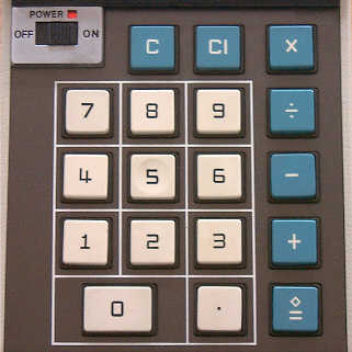
The keyboard of the Pocketronic was implemented using different technology than Van Tassel's original Cal Tech keyboard. By 1970, keyboard technology had come quite a long way, and Canon had other technologies for keyboards that were inexpensive and reliable for use in the Pocketronic. The layout of the Pocketronic's keyboard is very straightforward. The keyboard consists of a total of seventeen keys. The key caps use molded in legends, which eliminate the wear problems associated with screened-on key cap legends. The standard zero through nine and decimal keys are grouped together in conventional fashion. The four math function keys for addition, subtraction, multiplication and division are located to the right of the numeric keys. The [C] key (which clears the calculator), and the [CI] key, which clears any partially entered numbers (for entry error correction) are located above the numeric entry keys. Lastly, the [◇ =] key serves as a "calculate and print" function that completes any pending math operations, causes the final result to be printed, then clears the calculator for the next math operation. On the left side of the calculator, above the numeric keypad, is the power switch, a simple slide switch with a small window that shows red (via a red-painted area on the slider of the switch) when the power switch is in the "ON" position, and black when the switch is "OFF".
Thermal Tape Cartridge for Canon Pocketronic Above the keyboard is a plastic
magnifying window that allows the user to read what is printed on the tape.
The thermally-sensitive tape is provided in special cartridges that snap
into place in a slot at the top rear of the machine. The cartridges
are made of a tinted plastic, allowing the user easily see how much tape
is left in the cartridge. Each cartridge contains 80 meters (262 feet)
of tape, claimed to be good for about 3000 typical calculations.
When a cartridge is empty, it is simply discarded
and replaced with a new cartridge. Canon marketed five-packs of thermal
tape cartridges. Given that every operation was recorded on the tape,
having a good spare supply of thermal paper cartridges was a good idea.
Original Box for Canon Pocketronic Calculator The thermal printer in the Pocketronic
is of similar design to that used in the Cal Tech prototype. The Cal Tech
used a simple roll of the thermal paper which had to be placed inside the
machine and manually threaded through the paper path. This would have
proved tedious for consumer use. The result for the Pocketronic was the
thermal tape cartridge. The cartridge has a slot in its plastic housing
that allows the thermal print head to come into direct content with the
thermal tape. A felt pad attached to a spring steel tensioner strip provides
the pressure to push the thermal paper against the print head. Inside the
calculator, a solenoid-activated ratcheting assembly turning a rubber
capstan provides the transport that moves the strip of thermal paper
across the print head and out the side of the calculator. Characters are
rendered in a 5x7 dot-matrix pattern (as opposed to the less-readable
3x5 dot matrix pattern used in Cal Tech). The print head is composed of a
column of seven solid-state heating elements on a ceramic substrate that
heat the paper to form vertically-oriented dots on the thermally-sensitive
paper as the transport moves the tape through the
machine. The transport advances 7 steps to print a character, five steps which
print the five columns of dots that make up the character, and two blank steps
to form the spacing between characters. A serrated metal cutting bar on
the edge of the slot (on the left side of the calculator) where the tape exits
the machine allows for easy tearing off of the tape.
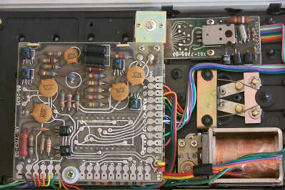
Inside the Pocketronic Internally, the Pocketronic is quite
simple. There are three small circuit boards that make up the electronics
of the machine. The circuit boards are connected to one-another as well
as to the keyboard via colorful ribbon cables. One circuit board provides
the master clock and timing circuitry, some power-supply conditioning circuits,
and the driver for the paper advance solenoid, all implemented using
discrete transistorized circuitry. Another board, sandwiched under the
clock/driver board, is the home of the three LSI (Large Scale Integration)
IC's that contain the logic of the calculator. Lastly, a third small
circuit board contains the discrete component driver circuitry for the thermal
print head.
The three Texas Instruments-made LSI's The circuit boards are made of fiberglass,
and have etch on both sides of the board, with plated-through feedthroughs
connecting the wiring on both sides of the circuit board. The LSI IC's
are packaged in ceramic dual-inline packages, with gold plated leads.
Two 40-pin devices (TMC1731 and TMC1732), and one 28-pin IC (TMC1730) make up
the IC's in the calculator. Date codes on these IC's place
their manufacture near the middle part of 1971.
Detail of the Clock/Solenoid Driver/Power Supply and Print head Driver Circuitry Along with the circuit boards, a small
solenoid (in the lower-right corner of the photo above) provides the kick that
advances the thermal paper, via a ratcheting mechanism. This
solenoid-activated paper advance system results in a very unique noise
as the paper is moved through the printing path and out of the calculator.
The noise is quiet enough to not be disturbing, and has an almost pleasant
rhythm to it. It takes about 2 seconds for the printer to print out a
complete 12-digit number, including sign and decimal point. The printer
prints out numbers and math operations as they are entered, allowing the
user to view the entries through the magnifying viewing window.
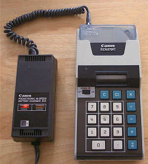
The Model 20A Hi-Speed Battery Charger with the Pocketronic The bottom half of the cabinet of
the Pocketronic contains
the Nickel-Cadmium battery packs that provide portable power for the calculator.
The batteries make up the bulk of the 1.8 pound mass of the machine.
A total of seven NiCd cells combine to provide the +7.2V and -8.4V supplies
that the machine operates on. The batteries are shielded from the rest
of the electronics in the machine by a metal shield, that also serves
to limit the RFI (Radio Frequency Interference) emanations created by the
logic of the calculator. The specifications for the calculator list a
run-time for the calculator of approximately three hours on a full charge of the
batteries.
Two different external battery
chargers were available for the Pocketronic. Both provide the ability to charge
the Nickel-Cadmium batteries in the machine. The Model 10A is
the standard device, in the form of a 'Wall-wart' style battery charger.
The Model 10A can only charge the batteries, and does not have sufficient power
to provide for AC operation of the calculator. The Model 20A "Hi-Speed" power
supply (pictured above) is a larger device that provides for charging of
of the NiCd batteries in the calculator as well as allowing the calculator
to operate from the AC line. The Model 20A charger also provides a much faster
charging time, putting a full charge on the batteries (with the calculator
off) in just three hours. The Model 10A charger takes about 13 hours to
bring the batteries to a full charge.
The Vinyl Carrying Case for the Pocketronic Operating the Pocketronic is very
straightforward. When the calculator is first turned on, the user manual
suggests that the [C] key should
be pressed to clear the machine and ready it for operation. The machine
prints a "C" on the tape when the calculator is cleared. Numeric entries are
then made, and are printed on the tape as each digit is entered. Pressing
a math function key results in the symbol for that operation to be printed
on the tape. Pressing the [◇ =] key terminates a calculation, printing
an equal sign (=) followed by the result of the calculation. For example,
performing the calculation 2.25 X 6.75 would be entered exactly as it
is written, followed by pressing the [◇ =] key. The output on the
tape would appear as: 2.25 X 6.75 = 15.8750 The actual operational speed of the
calculator is difficult to measure, as the printer limits the rate at
which the machine can operate. The specifications for the calculator
list "Calculating and Printing Time" as taking a maximum of 2 seconds.


Answers are printed
with leading zeroes suppressed. Trailing zeroes are not suppressed.
If a number is negative, a leading "-" is printed. Inputting a number
that is too large (greater than eight digits in front of the decimal point,
or more than 4 digits behind the decimal point) causes an input overflow
to occur, logically locking the keyboard such that no more digits can be input.
Pressing the [CI] key will unlock the keyboard, with the calculator
printing a "E" followed by a couple of spaces to indicate the fact
that the previous entry was cleared, along with clearing the numeric
entry register. If a calculation overflows the capacity of the machine,
a "C" is printed at the point of the overflow, and the calculator is
cleared.